The Internet is a network of computer networks communicating with each other using the TCP/IP protocol suite. Networking protocols are normally developed in layers, with each layer responsible for a different part of the communication. A protocol suite is a combination of protocols for different layers. TCP/IP is normally divided in the four conceptual layers illustrated in figure 3.1.
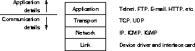
Figure 3.1: The four layers of the TCP/IP
protocol suite (From [25, section 1.2,]).
The International Organization for Standardization (ISO) has developed a reference model for describing the structure of networks and networking applications, known as the Open Systems Interconnection (OSI) model. This model consists of more layers compared to figure 3.1, but the traditional four layer system should be sufficient to give an overview of TCP/IP networking. For more on the OSI model, see for instance [26].
Data is moved across the network in units called packets. Each layer performs encapsulation by adding a header and possibly a trailer to the packets. Encapsulation information may include source and destination identification, packet size, checksums, and other controlling information.
The constructed layering offers the benefit of detail hiding: A layer provides a set of well-defined services to the layers above, and relies on the services provided by the layers below.
The link layer includes the networking card and the device driver
within the operating system kernel. The responsibility of this layer,
is to handle the hardware details. At this level, hosts are identified
using addresses stored in the interface card, known as
MAC![]() -addresses in the OSI-model
[26].
-addresses in the OSI-model
[26].
The network layer, sometimes called the internet layer, handles movement of packets around and between networks, including routing. Most network layers have a maximum packet size, based on the characteristics of the underlaying link layer. This is called the network's maximum transmission unit (MTU). When transferring packets exceeding the MTU, fragmentation may occur: The packet is split in two or more fragments. The destination network layer is responsible for reassembly of the fragments into the original packet [1].
IP addresses are introduced at the network layer, as an abstraction from the hardware addresses used at the link layer. The latter are used within a single, physical network only.
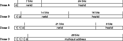
Figure 3.2: IP address classes (From [1, section
5.2.4,]).
Every host on the Internet must have a unique 32 bit IP address, encoding a network ID and a host ID. An IP address is typically written in dotted decimal notation, where the four bytes of the 32 bit number is written in decimal, separated by dots. To be able to scale for different size networks, the single host address space is divided in the three classes A to C for networks with varying numbers of hosts, according to figure 3.2. In addition, a separate class is defined for multicast addresses, along with a fifth class E (not in the figure) reserved for future use. The host part of the IP address may be split in a subnet ID part, and a host ID part [27]. This subnetting eases administration of physically separated networks within an organization.
Humans tend to prefer textual names to IP addresses, so a distributed database, the Domain Name System (DNS) [28][29] exists, mapping between names and addresses.
The transport layer provides a flow of data between two hosts, to be used at the application layer above it. Two transport protocols exists in the TCP/IP protocol suite:
TCP is used by many applications, such as Telnet, Rlogin, FTP and electronic mail (SMTP).
UDP is typically used for applications sending small amounts of independent data, like clock synchronizers and hostname lookup services, and for programs sending packets of full state info, like some networking games.
More than one process on a single host may use TCP or UDP at once. The operating system thus needs a way to identify the source and destination processes of TCP streams and UDP datagrams. A 16 bit port number, combined with the protocol type, is used for this identification. Standardized protocols use well known port numbers, published in the ``Assigned numbers'' RFC [32] by Internet Assigned Numbers Authority (IANA). As an example, a File Transfer Protocol (FTP) [33] client by default connects to TCP port 21 on the server host, since port 21 is the well known port number of FTP.
The application layer handles the application details, aided by the layers below. A class of applications will typically have a commonly defined protocol, describing how they are supposed to communicate. Examples include Simple Mail Transfer Protocol (SMTP) [34], setting a standard for communication between mail transport agents (MTA), and Hypertext Transfer Protocol (HTTP) [35] describing how a Web server and a Web browser does information exchange.
For a typical Unix system, the application layer will run as a user process, while the other layers are handled by the operating system kernel.
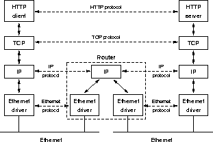
Figure 3.3: HTTP-transfer between two hosts on
different physical networks, connected using a router.
(Partially from [25, section 1.2,]).
Figure 3.3 shows how the different layers of two hosts communicate with each other. Although the data flows through the Ethernet cables, via the router and up or down the layers on each host, we can imagine a peer-to-peer connection between the matching layers on the two hosts, illustrated with stippled lines in the figure.
Bandwidth denotes the data transfer rate of a network line; the number of data units transferred in a given amount of time. The maximum bandwidth between two hosts, is determined by the hardware and accompaniment protocols used to connect the hosts in question. If data passes intermediate nodes, the maximum bandwidth is constrained to the one in the bottleneck; the link with lowest maximum bandwidth.
It may be important to distinguish between maximum bandwidth and available bandwidth. The available bandwidth depends on the number of connections sharing the same line, routing decisions, and on overhead from higher level protocols. In general, the available bandwidth on the Internet is unpredictable, as lines are shared between many users on different hosts, and TCP/IP doesn't support bandwidth reservations. In addition, routers may choose different paths for the packets comprising a connection.
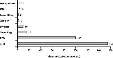
Figure 3.4: Maximum bandwidths for various
types of connections to the Internet (From [36]).
Figure 3.4 illustrates the maximum bandwidth on various types of link schemes used to connect nodes on the Internet. At present, analog modem and ISDN (Integrated Services Digital Network) are the most likely connection types for home users. A cable TV provider in Oslo has just recently announced that they will offer Internet connections using their cable network, in cooperation with an ISP. Ethernet, Token Ring and FDDI (Fiber Distributed Data Interface) are LANs, while Frame Relay and ATM (Asynchronous Transfer Mode) are used in Wide Area Networks (WAN).
The problem of varying available bandwidth, plays an important role when transferring real-time video over networks. A decreasing bandwidth may have to be compensated for by transferring less information, doing any combination of the following:
Robust schemes for real-time video should allow a running negotiation
between the sender and the receiver about data transfer rate and video
quality. The Real-Time Protocol (RTP), introduced in
section 3.4.1 on page ![]() , supports mechanisms
for this kind of negotiation.
, supports mechanisms
for this kind of negotiation.
In the following, it is important to know that on a Local Area Network (LAN), packets sent may normally be seen by all hosts. Packets not intended for the host in question, are filtered out by the network adaptor, the link layer of the TCP/IP protocol suite.
Traditionally, communication at the application layer of a network has been done between two hosts only; packets sent have an explicit destination. This one-to-one communication is called unicast.
Most LANs also provide some sort of broadcast, allowing sending
frames![]() simultaneously to all
hosts on the network. [37] specifies how broadcast is
extended to several connected networks on the Internet. Broadcasts are
typically used when converting from IP to hardware addresses using ARP
(Address Resolution Protocol) [38], or from hardware
addresses to IP addresses using RARP (Reverse Address Resolution
Protocol) [39].
simultaneously to all
hosts on the network. [37] specifies how broadcast is
extended to several connected networks on the Internet. Broadcasts are
typically used when converting from IP to hardware addresses using ARP
(Address Resolution Protocol) [38], or from hardware
addresses to IP addresses using RARP (Reverse Address Resolution
Protocol) [39].
Modern network interfaces also provide multicast [25]. With multicast, packets are accepted by hosts that are members of addressed multicast groups. The filtering of packets is done as a cooperation between the link layer and the IP layer [25]. Multicast is used for delivering packets to multiple destinations in applications for video conferencing and radio and TV transmissions. Bandwidth savings can be achieved compared to unicast, since each package is transmitted only once within LANs. Multicasting on the Internet is described in [40] and [41].
The various cast types are distinguished using hardware addresses on the link layer, and IP addresses on higher layers. Separate sets of IP addresses are used for unicast (classes A to C), multicast (class D) and broadcast. IANA describes the sets and reserves some multicast addresses as ``well known addresses'' in [32].